Thiết Kế Tuabin Gió
Nguyên tắc và cân nhắc trong thiết kế tuabin gió
Nâng Cao
29 phút đọc
Giới Thiệu
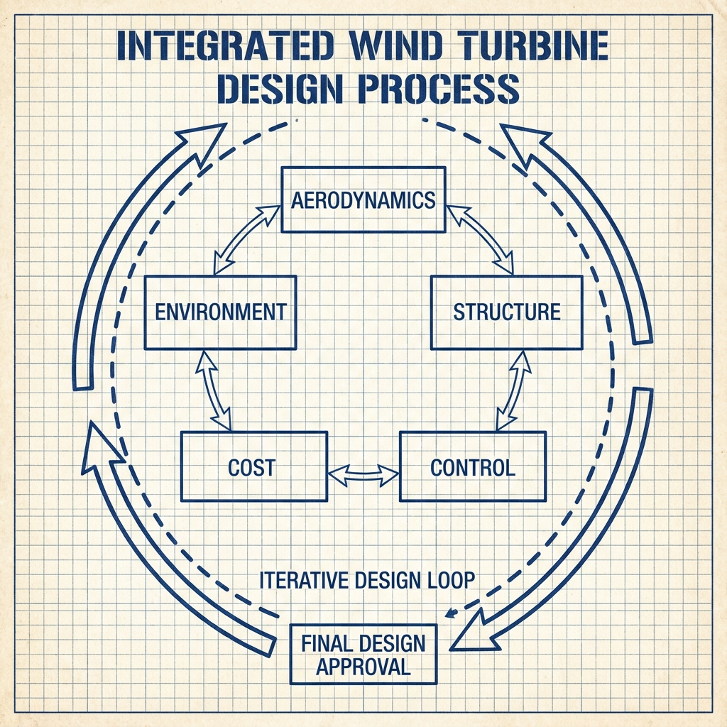
Thiết kế tuabin gió là một quá trình tối ưu hóa đa mục tiêu (multi-objective optimization) phức tạp, đòi hỏi sự cân bằng giữa hiệu suất khí động học, độ bền kết cấu cơ khí, chi phí sản xuất và tác động đến môi trường. Chương này sẽ đi sâu vào các nguyên lý thiết kế, từ lý thuyết cơ bản đến các ứng dụng thực tiễn.
Mục Tiêu Thiết Kế
Các yêu cầu mang tính cạnh tranh:
- Tối đa hóa AEP (Sản lượng Năng lượng Hàng năm - Annual Energy Production)
- Tối thiểu hóa COE (Giá thành Năng lượng quy dẫn - Cost of Energy)
- Đảm bảo độ tin cậy (tuổi thọ thiết kế 20-25 năm)
- Tuân thủ các tiêu chuẩn kỹ thuật (IEC 61400, tiêu chuẩn GL)
- Giảm thiểu tác động môi trường (tiếng ồn, cảnh quan)
Giới Thiệu
Thiết kế tuabin gió là một quá trình tối ưu hóa đa mục tiêu (multi-objective optimization) phức tạp, đòi hỏi sự cân bằng giữa hiệu suất khí động học, độ bền kết cấu cơ khí, chi phí sản xuất và tác động đến môi trường. Chương này sẽ đi sâu vào các nguyên lý thiết kế, từ lý thuyết cơ bản đến các ứng dụng thực tiễn.
Mục Tiêu Thiết Kế
Các yêu cầu mang tính cạnh tranh:
- Tối đa hóa AEP (Sản lượng Năng lượng Hàng năm - Annual Energy Production)
- Tối thiểu hóa COE (Giá thành Năng lượng quy dẫn - Cost of Energy)
- Đảm bảo độ tin cậy (tuổi thọ thiết kế 20-25 năm)
- Tuân thủ các tiêu chuẩn kỹ thuật (IEC 61400, tiêu chuẩn GL)
- Giảm thiểu tác động môi trường (tiếng ồn, cảnh quan)